DIY Self Driving - Part 5 - Sensors

Please Note: Unlike most of my projects which are fully complete before they are published, this project is as much a build diary as anything else. Whilst I am attempting to clearly document the processes, this is not a step-by-step guide, and later articles may well contradict earlier instructions.
If you decide you want to duplicate my build, please read through all the relevant articles before you start.
For navigation, here are two sensor types in the car at this stage, a video camera and ultrasonic. The video camera is the heart of the control and navigation and will be covered in detail in the software article. The ultrasonics are used to augment the data from the camera.
While the camera feeds a live stream into a Raspberry Pi which runs an OpenCV application to detect the road as well as obstacles, I have not (yet anyway) worked out how to judge distance from this information. This is where the ultrasonics come in. I have used these devices (HC-SR01) in previous projects and they are tough and reliable. The purpose here is to give an indication of the distance to any objects immediately in the car's path.
At present, detecting an object with the ultrasonics will bring the car to a halt until the obstacle is cleared. This isn't a perfect solution but it gets me started.
When choosing the location for the ultrasonics make sure it has an uninterrupted "view" ahead. This is essential to prevent false echoes being received.
Mounting the ultrasonic module is not too difficult as there is a fair amount of room behind the front bumper. However, in my car I needed to mount it PINS DOWN so as to clear the upper mount and the attachment for the bonnet (hood). It was also necessary to bend the connecting pins back to a straight position so that the are at right angles to the board. If I left them pointing to the bottom of the module there will not be enough room for cable attachment.
Take your time when mounting the ultrasonic module as it will be quite visible on the finished product, and the plastic is soft and easily over-cut.
 |
| Mounting front ultrasonics |
The ultrasonic module is connected to the Arduino which uses the "NewPing" library to manage the ranging functions.
More challenging is mounting the camera. I started out with a Logitech HD camera which produced very good results, but is rather large and did not lend itself to mounting on the car. Recently I switched to a bare 4K module using a Sony image sensor. Both cameras use a USB interface to the Raspberry Pi. As with the ultrasonic module the camera must be obstruction free, and take into account the following:
- It must not have any part of the vehicle in the frame as this can disturb the detection logic.
- It must be mounted and aligned along the longitudinal centreline of the car.
- Any reflective parts of the car should be masked to prevent cross-lighting.
- You will need to experiment with a slight downwards angle to get the best result.
Because it is a bare module it needs to be protected from the elements as well as from impacts I am also trying to make it look less "stuck on", but it's still a work in progress.
 |
| Logitech camera works well, but it looks wrong because of the big bracket |
 |
| Custom 4K module gives a better fit and image quality |
If you look closely at the photo you will notice that the camera module is attached with "Blu-Tak". This is purely temporary (I hope) whilst I create a better mounting arrangement.
When choosing a camera, if possible choose one with an auto-iris function. This will help when the car is driving towards the sun. Also it needs to be mounted securely so as to minimise vibration effects. Better frame rates can be achieved using a CSI-connected camera such as the dedicated Raspberry Pi unit. However its shorter built-in cable will make mounting more difficult. If you can work out how to do it, all the better.
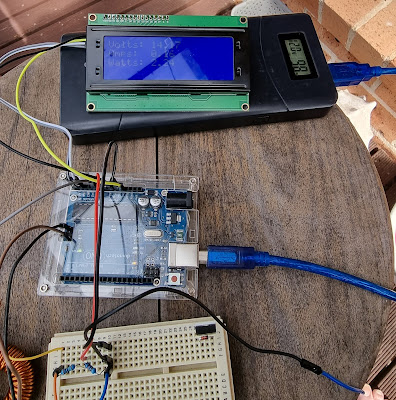
To get a better understanding of the performance, I also added an Allegro ACS712 current sensor. These are available in a number of current ratings from 20 to 100A. My unit is a 30A module. It is very simply to use. Take the voltage from the sensor, subtract the offset voltage (2.5V) because the sensor can read current flow in each direction and divide the mV value by 66 to get the DC current in amps. My motor starts up at around 2.6A and settles down to a steady current when running of around 1.5A.
Further Reading
Part 1 - Introduction
Part 2 - Preparing the car
Part 3 - Wiring Harnesses
Part 4 - Steering
Part 6 - Software
Part 7 - Final assembly and testing


Comments
Post a Comment